Vector measurement and performance tuning of a terahertz bottle beam-3
Vector characteristics of a THz bottle beam
Taking advantage of the vector characterization function of the THz imaging system, the diffraction properties of the Ez component are measured and analyzed for the THz bottle beam. The identical x-linearly polarized THz bottle beam is formed by applying the Teflon axicon with α = 20° as well as the silicon lens with f = 8 mm and its Ezcomponent with 0.75 THz is extracted. By fulfilling the Z-scan scheme, the evolution of Ez is coherently recorded. Figure 4a exhibits the amplitude distributions of Ez on the x-y plane at z = −4.5 mm, −2 mm, 0 mm, 2 mm, 4.5 mm and the amplitude cross-section on the x-z plane. The Ez component shows interesting distribution characteristics. At z = −4.5 mm, the Ez component possesses two off-axis main-lobes at x = ±0.33 mm as well as several crescent side-lobes, which presents a bilateral symmetric amplitude distribution. The amplitude maximum of Ez is approximately 25% of Ex. Around the optical axis, there is a zero-amplitude zone. With increasing the propagation distance, the structure of the Ez component starts to become ambiguous. At z = −2 mm, the off-axis main-lobes as well as the inner side-lobes have mixed together and the outer side-lobes show a converging trend to the inside. When the THz beam propagates to z = 0 mm, the Ez component exhibits two pairs of crescent amplitude patterns, which shows a mirror symmetric configuration. Each pair of the amplitude patterns separately locates on the left and right sides of x = ±1.23 mm. After passing through the focal plane, the THz beam undergoes an inverse evolution process. The longitudinal amplitude pattern more clearly manifests the variation of Ez during the formation of the THz bottle beam. To explain the phenomena, the transverse wave vectors are induced and Ez is generated in the focusing region of the THz beam. Furthermore, Ez should present the intensity distributions on the two sides of the corresponding focal spot of Ex for the linearly polarized focusing THz beam22. At z = −4.5 mm and 4.5 mm, Ex manifests the distribution pattern of a Bessel-like beam, including a circular central peak and ring-shaped side-lobes. Therefore, the corresponding Ezcomponent shows off-axis main-lobes and crescent side-lobes, which are in agreement with our previous report18. On the focal plane (z = 0 mm), the focal spot of Ex locates on the position of the THz light ring, so the Ez intensities appear on the two sides of the THz light ring. In addition, there is no any Ez component on the y-z plane because the THz polarization is along the x direction22. Figure 4b show the transverse wrapped phase patterns of Ez at z = −4.5 mm, −2 mm, 0 mm, 2 mm, 4.5 mm and the longitudinal phase cross-section. The phase of Ezmanifests a complicated distribution which consists of several semi-ring regions. These semi-ring regions exhibit a mirror symmetric distribution with respect to the y axis. Besides, it is not difficult to find that there is always a phase jump of π between the corresponding left and right semi-ring regions. It means that the propagation directions of the Ez components are always opposite on the two sides of the y-z plane. By utilizing Eqs (3–9), the simulated amplitude and phase images of Ez are acquired. Figure 4c,d show the calculated results at z = −4.5 mm, −2 mm, 0 mm, 2 mm, 4.5 mm and the longitudinal amplitude and phase cross-sections, which are in accordance with the measured results. Besides, it should be also noted that there is not a tight-focusing process during the formation of the THz bottle beam, so the polarization of the THz field is not influenced and the Ey component can be negligible23.
Complex field pattern of Ez with 0.75 THz for the linearly polarized THz bottle beam. (a,b)show the Ez amplitude and wrapped phase images on the x-y plane at z = −4.5 mm, −2 mm, 0 mm, 2 mm, 4.5 mm. The Ez amplitude and phase cross-sections on the x-z plane are also extracted and presented. (c,d) give the corresponding simulated Ez amplitude and phase patterns.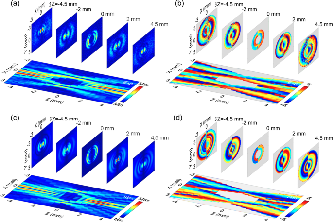
In the work, the Ez component is also observed for a THz bottle beam with a circular polarization. By inserting the quartz TQWP into the path of the incoming THz beam, the left circularly polarized THz bottle beam is generated and the complex field of its Ez component is coherently recorded. Figure 5a gives the amplitude images of Ez on the x-y plane at z = −4.5 mm, 0 mm, 4.5 mm, respectively. The Ez component shows similar amplitude distributions at z = −4.5 mm and 4.5 mm, including a central doughnut-shaped intensity and some weak annular side-lobes. On the focal plane (z = 0 mm), the Ez component obviously exhibits two concentric light rings. Figure 5b shows the wrapped phase patterns at z = −4.5 mm, 0 mm, 4.5 mm, which clearly present vortex modalities. Their phase values linearly increase in a clockwise sense. Besides, the twist sense of the Ez phase exhibits a reverse after propagating through the focal plane. Actually, the phase characteristics are analogous to the Ezphase properties of a converging circularly polarized THz Gaussian beam22. When the polarization of a focusing light beam is adjusted as the circular polarization, both Ez components are excited on the x-z and y-z planes. Simultaneously, there is a phase delay of π/2 between them. Ultimately, their interference effect forms the annular amplitude and the spiral phase. According to our previous reports18, a general law has been summarized for the Ez component of a converging light beam. Namely, when a light beam emerges through a set of axial symmetrical wave front modulators, Ez with a linear or a circular polarization presents a double-lobe characteristics or a vortex mode. Obviously, the Teflon axicon and the silicon lens possess the amplitude and phase modulations with an axial symmetry to the incoming THz beam, so the formed THz bottle beam conforms to the general law. The complex field of Ez with a circular polarization can be viewed as the linear superposition of Exz and Eyz. Herein, Exz and Eyz are longitudinal components of two THz bottle beams with perpendicular linear polarizations. Accordingly, Ez with the left circular polarization can be written as
(10)
Complex field pattern of Ez for the THz bottle beam with a left circular polarization. (a,b)Present the amplitude and wrapped phase patterns of Ez at z = −4.5 mm, 0 mm, 4.5 mm on the x-y plane. (c,d) Give the simulated results.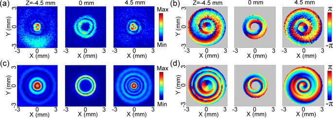
The calculated amplitude and phase images of Ez at z = −4.5 mm, 0 mm, 4.5 mm are given in Fig. 5c,d, which are in accordance with the measured phenomena.
Performance tuning of a THz bottle beam
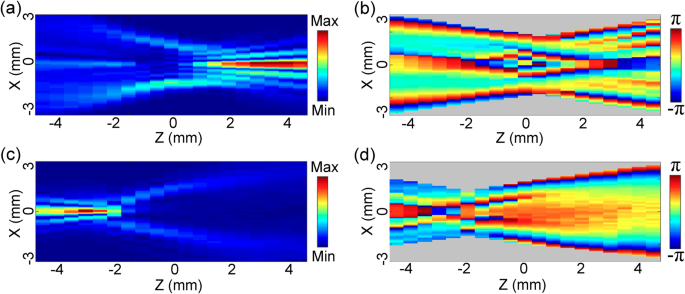
If the parameters of the Teflon axicon and the silicon lens are tuned, the characteristics of the formed THz bottle beam can be effectively modulated. Firstly, the distance z0 between the Teflon axicon with α = 20° and the silicon lens with f = 8 mm are adjusted to observe the variation of the THz bottle beam. Figure 6a and c separately give the longitudinal amplitude patterns of Ex with 0.75 THz when z0 are set as 56 mm and 6 mm. Interestingly, the forward optical barrier (the central peak at z = −4.5 mm) of the THz bottle beam is diminished when z0 is equal to 56 mm. Meanwhile, the backward optical barrier (the central peak at z = 4.5 mm) is attenuated if z0 is adjusted to 6 mm. To explain these phenomena, the THz beam refracted by the Teflon axicon forms a series of THz plane waves propagating along different directions, which emerge through the silicon lens and generate the THz bottle beam if f < z0 < Zmax. When the distance z0 is too large, these converging THz beams after passing through the silicon lens cannot overlap with each other so that the forward optical barrier disappears. In the same way, when the distance z0 is too small, these diverging THz beams after propagating through the focal plane cannot overlap with each other, so the backward optical barrier vanishes. Figure 6b,d exhibit the longitudinal wrapped phase cross-sections of Ex with z0 = 56 mm and 6 mm, which also clearly manifest these processes. When z0 is set as 56 mm or 6 mm, the phase pattern only expresses the obvious interference around z = 4.5 mm or −4.5 mm, respectively. Therefore, it can be concluded that the opening direction of the THz optical barrier can be readily controlled by adjusting the distance between the Teflon axicon and the silicon lens.
Modulation of the THz bottle beam by varying the distance between the Teflon axicon and the silicon lens. (a,b) Present the longitudinal Ex amplitude and wrapped phase cross-sections when the distance is adjusted as 56 mm. (c,d) Show the Ex amplitude and phase patterns on the x-z plane when the distance is set as 6 mm.