5G/NR - OTA (三)
Probably by now, you may have a question 'Why do we need to test in Far Field ?'. It would not be easy to get a direct answer to this question. So let me change the question a little bit. Why we do not test in Near field ?
The simple answer to this question is that the measurement result in this region tend to be unpredictable and subject to change with small changes in the environment surrounding the antenna(e.g, electrical circuit feeding the antenna) and location changes. On the contrary, the field pattern in Far field is more stable and predictable and less senstive to small surrounding components.
For those who are interested in further details, let's look a little bit further details on the characteristics in each of the region. You may investigate even further on your own. Try googling the keywords like 'Near and Far Field', 'Field Region around Antenna' etc.
Reactive Near Filed : This is the area that is very close to the antenna. The relationship between E and H field in this region is very unpredictable (It is unpredictable not because this property goes against a physical theory, but because the physical property is so complicated). For example, at one point you would see E field dominates and at another point right besides the previous point H field dominates. Also radiated energy would influence back and forth with surrounding electrical component like antenna control circuit. For example, some portions of radiated energy gets absorbed and stored in surrounding component at some point of time and the stored energy gets radiated back into the space at other point of time and influence radiation pattern.
Radiative near field (Fresnel region) : In this region, the distance from the antenna is not so close to be influenced by reative electrical components as described above and the E and H field relationship is much more predictable comparing to Reactive Near Field. However, the E and H field relationship is still pretty complex and there are high possibilities where some physical object that may affect the radiation pattern in this area. For example, some metal object like steel beam holding up the antenna module can act as a kind of antenna or reflector. So this kind of object can influence on the radiation pattern of the AUT(Antenna Under Test).
FAR field (Fraunhofer region): In this region, the angular field distribution is essentially independent of the distance from the antenna and the radiation pattern can be approximated with spherical wave-fronts. Since any recieving point in the region are very far from the antenna, the transmitter size and shape are not important anymore and it can be approximated as a point source. The electric and magnetic fields are in phase, perpendicular to each other and perpendicular also to the direction of propagation. In this region, you can safely assume that the wave front going through the recieving antenna is planner (i.e, all the incoming rays are in parallel to each other). Putting it simple, this is the idea region in which most of measurement can be done easily and reliably.
Why Antenna Dimension is so important ?
As mentioned above, in order to achieve the stable measurement result it is important to put the distance between DUT antenna and the equipment antenna to be greater than the Far Field Boundary. As shound in [Figure 1], the Far Field boundary starts from the following distance.
![]()
As you notice from this expression, the distance is proportional to D squared (D represents antenna dimension). That is, the distance changes drastically with even a small changes in D. To give you more intuitive understanding, I plotted this equation in a graph as shown in left. The path loss at the boundary also increases as the D increases as shown in right.
< Figure 5 - Far Field Distance and Path Loss with D >
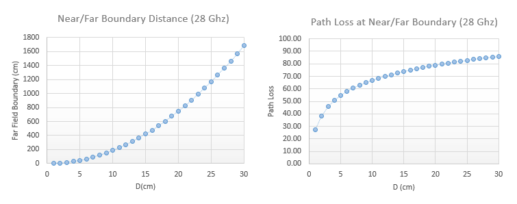
In case that you want to get the exact quantitative data, I put a table as shown below. The two graphs shown above are plotted from this table.
< Table 2 - D influencing on Far Field Distance and Path Loss >
D(cm) | Freq(Ghz) |
| Path Loss |
1 | 28 | 2 | 27.42 |
2 | 28 | 7 | 38.30 |
3 | 28 | 17 | 46.01 |
4 | 28 | 30 | 50.94 |
5 | 28 | 47 | 54.84 |
6 | 28 | 67 | 57.92 |
7 | 28 | 91 | 60.58 |
8 | 28 | 119 | 62.91 |
9 | 28 | 151 | 64.98 |
10 | 28 | 187 | 66.83 |
11 | 28 | 226 | 68.48 |
12 | 28 | 269 | 69.99 |
13 | 28 | 315 | 71.36 |
14 | 28 | 366 | 72.67 |
15 | 28 | 420 | 73.86 |
16 | 28 | 478 | 74.99 |
17 | 28 | 539 | 76.03 |
18 | 28 | 605 | 77.03 |
19 | 28 | 674 | 77.97 |
20 | 28 | 747 | 78.86 |
21 | 28 | 823 | 79.70 |
22 | 28 | 903 | 80.51 |
23 | 28 | 987 | 81.28 |
24 | 28 | 1075 | 82.02 |
25 | 28 | 1167 | 82.74 |
26 | 28 | 1262 | 83.42 |
27 | 28 | 1361 | 84.07 |
28 | 28 | 1463 | 84.70 |
29 | 28 | 1570 | 85.31 |
30 | 28 | 1680 | 85.90 |
What this implies is that you need to know the exact antenna dimension in order to get the accurate measurement. However, it is not always easy to correctly define the antenna dimension. Antenna Dimension D is defined as the maximum distance across the whole antenna module. The Red Arrow in [Figure 6] indicates D. As you see, it would be straightforward to define D in case of (A), (B), (C) and (E). However, in case of (D), defining the dimension would not be so easy. In (D), the physical dimension is same as (A), but you see some conductive material around the antenna module influence the radiation pattern of the antenna module. This may influence the effective dimension of the antenna and it would be very difficult to accurately estimate the effective dimension. Also there would be some possibilities where UE makers distribute the antenna modules accross several different locations inside of the UE as shown in (F), (G) and (H). Of course, the shape and location of Antenna modules within a UE would be more diverse and complicated than the ones shown here.