


5G/NR - OTA (四)
< Figure 6 - Antenna Dimensions for various configuration >
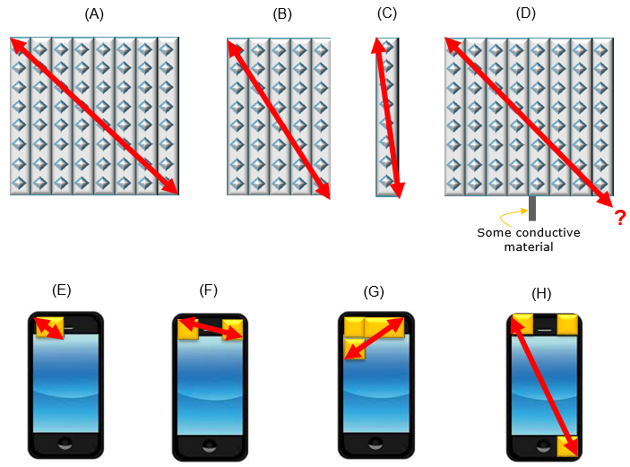
There is another reason why defining D gets difficult. It would get more difficult for UE case. In order to correctly define D, you need to have all the detailed information of the antenna structure and positions in UE. But in many cases these information is treated as a highly confidential information by most of UE manufacturer. So when you are given a UE (especially a commercialized UE), it is almost impossible to get the exact estimate for D (Dimension).
Now we are facing a very tricky situation. How can we guarantee the accurate measurement when we are not given the detailed information on Antenna dimension ?
This is what I will talk about next section.
Handling Known-D situation and Unknown-D situation (Whitebox vs Blackbox Approach)
Before getting into specific cases, let's think of the meaning of a few basic words - Whitebox and Blackbox. Whitebox refer to a box we can directly look into the box and clearly knows what is inside of the box. It means all the information about the box is known to ux. Blackbox refer to a box we have no direct visibility to the inside of the box. The only way that we can figure out the contents of the box is via indirect observation like shaking the box and listen to the sound or lifting up and estimate the weight etc. Of course, this is not the formal definition of Whitebox and Blackbox in OTA, but the basic idea applies to the formal definition as described in R4-1708553 (Ref [4]).
For the ”Black box” approach, the exact antenna locations/centre-of-Radiation-Reference-Point (CORRP) do not need to be known.
The UE is positioned with a common reference point similar to existing SISO OTA test cases
Execution of test cases have relatively low complexity (repositioning to CORRP will not be necessary)
An MU element for “Offset DUT phase centre from centre of QZ(Quiet Zone)” will need to be added for the DUT stage of the MU budget which depends on size of QZ, and range length
For the ”White box” approach, the exact antenna locations/centre-of-Radiation-Reference-Point (CORRP) need to be known, likely via a manufacturer declaration.
The CORRP for the active antenna array needs to be aligned with the centre of the quiet zone which likely yields complex execution of test cases
An MU element for “Offset DUT phase centre from centre of QZ(Quiet Zone)” will not need to be added for the DUT stage but a MU element for UE re-positioning needs to be added
Now you may ask 'Why we are talking about whitebox / blackbox concept here ?' and 'how are they related to handling D(Antenna Dimension) ?'. Let's think of a situation where we have the detailed information on D and a situation where we don't have exact information on D.
Let's assume that we have all the detailed information about D. It means the Antenna module under test is a kind of whitebox. In this case, we can calculate the exact location of Near / Far boundary. Then we can get relatively accurate measurement with the minimum distance between DUT and Measurement Antenna(Probe) and still meeting the Far field criteria as in (A) of [Figure 6]. It means that we can meet the Far Field condition with minimum size of Anechoic chamber. In turn, it means we can get the accurate measurement with minimized cost on Anechoic chamber.
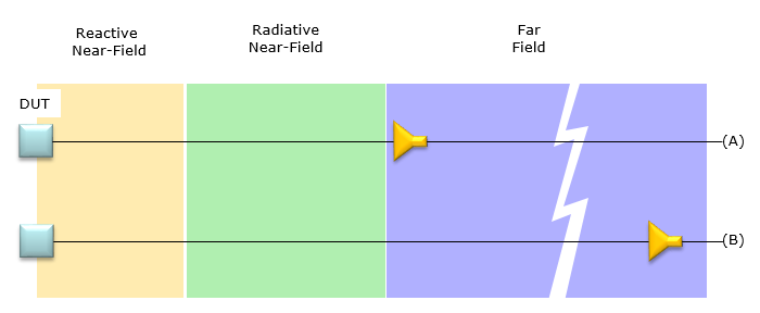
Now let's think of a situation where we don't have accurate information on D. How we can estimate the exact location of Near/Far boundary (i.e, Starting point of Far Field) ? The answer is 'There is no way to do it'. Then how we can guarantee that the antenna is in Far Field ? The simplest way is to place the receving antenna at a position which is very far away from the DUT so that you can assume that it is in Far field regardless of the size of antenna as in (B) of Figure 6. Of course there should be a certain limitation of Antenna size you assume. You would not assume that the antenna size is 20 cm when you have a mobile phone with the size of 10 cm.
< Figure 6 : Possible Antenna Location in Whitebox and Blackbox condition >
Wrapping up,
we may say if we can get the detailed information on Antenna dimension and exact antenna location on DUT (e.g, Mobile phone), it would be better to use Whitebox approach, since we can do the measurement with smaller chamber and at relatively low cost. This can be a good option at the development stage in which these informations tend to be open.
If the detailed information on Antenna dimesion and locations on Mobile phone, Blackbox approach will be the better option. Since most of the mobile phone manufacturer would be very reluctant to open the detailed information on antenna on their commercialized device, the blackbox approach may be the only option for the commercialized device. However, as mentioned above, we would need very large chamber to apply the blackbox approach which would cause cost and space issue. To mitigate this problem, an alternative concept were proposed and this alternative will be explained in next section.
NOTE : Regarding the adoption of Whitebox approach or Blackbox approach, Ref [3] states as follows :
For conformance testing, 3GPP has decided that only the black box approach can be used. This is due to the requirements for white box testing not being accepted by UE vendors who preferred not to declare the antenna structure.
Emulating a Black Box with Not-Too Big Chamber - CATR
As mentioned above, it is likely for only blackbox approach to be accepted as a test method for commercialized device since UE manufacturer does not like to disclose the detailed antenna information, but blackbox approach tend to require huge chamber (i.e, large distance between the transmitter and reciever antenna). To reduce the problem of the chamber size issue an alternative concept called CATR(Compact Area Test Range). The overall concept is described in TR 37.842 as shown below.
< TR 37.842 - Figure 10.3.1.1.3.1-1: CATR measurement system setup for EIRP >
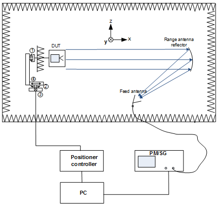
As shown above, you will see the signal from the transmitter antenna bounces (reflects) from a specially designed reflector and then reaches to the receiver antenna. This would take an effect of folding up a long linear distance into a small space, which result in reducing the size of the chamber. In addition, by designining the reflector in a specific form, you can make all the parallel rays from DUT reaches to Feed antenna(measurement antenna). And, also you can make the rays from the feed antenna reaches DUT as parallel rays. Actually the basic principle is similar to what you learned in high school physics about Ray diagram of Parabolic mirror. Try googleing 'Parabolic Mirror Ray Diagram' or 'Parabolic Mirror Ray Tracing' etc.
Reference
[1] 3GPP TSG-RAN WG5 Adhoc Meeting#1 - R5-180013 : Signalling NR Testcases - OTA chamber requirements
[2] Near and far field (Wikipedia)
[3] Keysight Technologies - OTA Test for Millimeter-Wave 5G NR Devices and Systems (White Paper)
[4] 3GPP TSG-RAN WG4 Meeting #84 - R4-1708553 : Far field definition and proposal for alternate RF baseline with deterministic antenna array positioning
[5] 3GPP TSG RAN WG4 Meeting NR#2 - R4-1706617 : Center of Radiation Reference Point – Reference Definition for OTA Measurements of Phased Array Beamforming Patterns
[6] 3GPP TR 37.842 V13.2.0 (2017-03) - Radio Frequency (RF) requirement background for Active Antenna System (AAS) Base Station (BS)(Release 13)
