


使用量子级联激光器的可调谐长波红外陷波滤波器的...-2
4.
Computational Modeling and Design
To predict the wideband electromagnetic properties of the LWIR GMRFs, we chose to implement the rigorous couple wave algorithm (RCWA) originally presented by Moharam and Gaylord.10,11 Our specific implementation is based on the enhanced transmittance matrix approach introduced by Moharam et al.12 and later refined by Lalanne4,13 and Noponen and Turunen.14
Using this method, the solution domain is divided into discrete infinite planar regions (i.e., incident region, exit region, and layered grating regions) and solved using a modal expansion methodology. For details on the specific implementation of the RCWA, the reader is referred to Refs. 1011.12.13.–14. RCWA simulation results provide a full-wave solution for all reflected and transmitted diffractive orders. However, if the grating periods are small compared with the incident wavelength (), as is the case for our GMRF designs, only the zeroth diffractive orders will propagate (i.e., all other diffractive orders will be evanescent). Thus, the filters will reflect and transmit light only in the specular directions. This condition is written mathematically as
Eq. (2)
Our custom RCW code, developed using the MATLAB programming environment, was used to calculate the complex transmission and reflection coefficients for the GMRF designs.
5.
Simulation Results
The RCWA method was used to design and simulate a GMRF within the LWIR band from 8 to . We used a 1-mm-thick ZnSe substrate with refractive index of 2.41, a Ge waveguide and grating with refractive index equal to 4.0, and a simple two-layer AR coating consisting of Ge and ZnSe layers applied to the bottom of the substrate. The specific geometry of the 1-D GMRF is shown in Fig. 3, and the layer structure and periodic feature used are shown in Table 1. As mentioned, is the grating period, W is the width of Ge grating groove equal to the fill factor times the grating period, is the thickness of the planar Ge waveguide, is the thickness of the Ge grating groove, is the thickness of the ZnSe substrate, is the thickness of the Ge layer, and is the thickness of the ZnSe layer in the AR coating. Such a filter is polarization-sensitive and to make a polarization-insensitive filter we need to use a 2-D grating. We used the parameters listed in Table 1 to carry out simulations for spectral transmittance of 1-D GMRF for both transverse electric (TE) and transverse magnetic (TM) polarizations of incident light for four different angles of incidence.
Table 1
Geometrical parameters used for GMRF simulation with 1-D grating structure.
| Λx (μm) | W (μm) | hwg (μm) | hg (μm) | hs (μm) | hAR1 (μm) | hAR2 (μm) |
|---|---|---|---|---|---|---|
| 2.85 | 1.14 | 1 | 0.5 | 1000 | 0.3 | 1.3 |
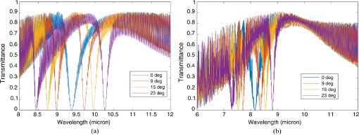
In Fig. 4, results are shown for theoretically simulated values of spectral transmittance and reflectance for TE and TM polarizations of the incident light at four different angles of incidence, 0 deg, 9 deg, 15 deg, and 23 deg, respectively. The device parameters were chosen to optimize the filtering operation for the TE polarization when the orientation of the incident light is parallel to the linear grating structure. Several key observations can be made based on these simulated results. The filter is tunable over the full 8- to spectral region. A very strong () reflectance can be achieved at resonance wavelength using this relatively simple 1-D structure. The line width of such a resonance can be tuned by varying the thickness of the grating. Also, the spectral location of the resonance peak can be tuned by tilting the device (i.e., changing the angle of incidence), which can be done mechanically. However, the single resonance seen at normal incidence splits into two resonances as the device is tilted with respect to the incidence wave. Given the nature of the 1-D grating design, the optical response is polarization sensitive as expected. While both TE and TM polarizations resulted in tunable GMR notch filter responses, the resonance wavelengths are not the same. For less polarization sensitive filters, we are currently exploring the use of 2-D gratings. Lastly, a high-frequency oscillation is seen in the simulated data due to Fabry–Perot fringing in the thick ZnSe substrate layer. While we did apply an AR coating to the backside of the substrate, the simple nonideal two-layer design we implemented was not very effective. We carried out simulations using multiple layer AR coatings to understand their effect and improve the filter design as discussed next.
Fig. 4Download
Simulated spectral transmittance plots using the RCWA method for the device parameters listed in Table 1. (a) Incident polarization is along the grating axis (i.e., TE) and (b) incident polarization is perpendicular to the grating axis (i.e., TM). The four curves are for incidence angles: 0 deg, 9 deg, 15 deg, and 23 deg.
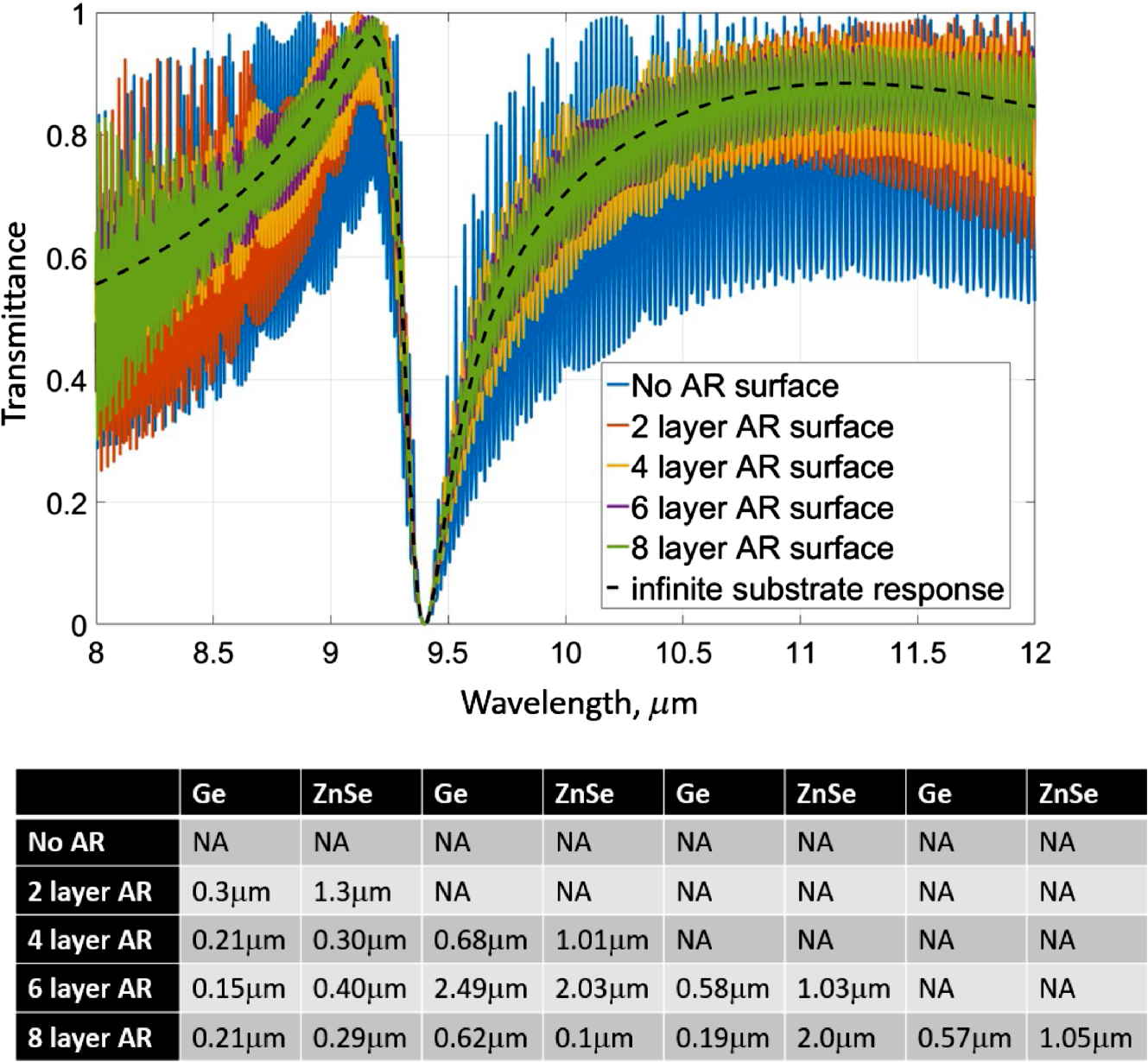
As shown in Fig. 5, Fabry–Perot fringing can be markedly reduced by improvements to the AR coating on the backside of the ZnSe substrate. This figure shows that as the number of coating layers is increased, the effectiveness of the AR treatment improves. As discussed above, for our current design used for fabrication, we implemented a simple two-layer AR coating. This was chosen primarily to simplify our fabrication process. However, an optimized eight-layer design would significantly reduce the backside reflections and thus reduce the magnitude of the Fabry–Perot fringes. We should also note that there are other methods that can be employed to reduce the effect of backside reflections including creating a slight wedge to the substrate so that the two surfaces are not parallel. Even a degree or two off parallel will have a large effect on reducing the fringes. We are, currently, exploring these methods experimentally.
Fig. 5Download
To minimize the Fabry–Perot fringing effect more sophisticated AR surface designs can be implemented. The top plot shows simulation results of how increasing the number of AR coatings layers from two layers (our current design) to eight layers significantly reduces back reflections from the thick ZnSe substrate and thus a large reduction in the magnitude of the Fabry–Perot fringes. Also shown in the figure (black dashed line) is the ideal filter response if the substrate was infinitely thick (i.e., no back reflections). A table is included listing the number of Ge and ZnSe layers and thicknesses used in the simulations.

