


使用量子级联激光器的可调谐长波红外陷波滤波器的...-3
6.
Performance Characterization Experiment
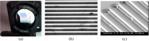
The prototype filters were fabricated based on the device design shown in Fig. 3 and the specifications listed in Table 1 using standard dielectric deposition and photolithographic techniques and delivered to our laboratory at the US Army Research Laboratory for characterization. A 1-in.-diameter ZnSe substrate polished on both sides with 1-mm thickness was used. The filtering device dimension is 13×13 mm2. We conducted detailed metrology of the devices using an optical microscope, a scanning electron microscope (SEM), and a profilometer.
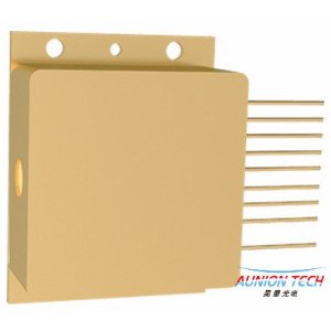
Figure 6 shows a photograph of the fabricated device mounted in a holder, an optical microscope image, and a SEM picture for a 1-D filter. The profile of the grating was measured using a Veeco profilometer. The profilometer measured the grating period to be 2.85 μm for a 1-D GMRF.
Fig. 6Download
(a–c) Photo of 13-×13-mm2 filter, optical microscope picture of a fabricated device, and an SEM image.
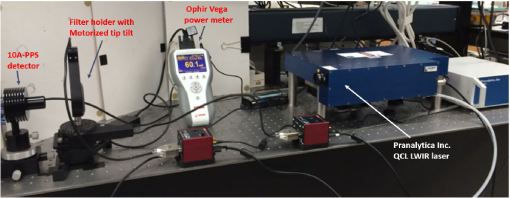
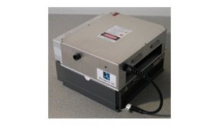
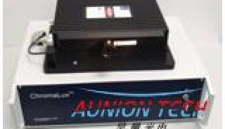
Traditionally, a Fourier transform infrared (FTIR) spectrometer is used to measure filter transmission. The FTIR spectrometer in our laboratory operates with incident beam focused on the sample and to obtain a collimated beam as required for plane wave incidence needs a major upgrade. Instead of using this FTIR spectrometer, we chose to use a QCL system that is tunable over the full range of filter operation to carry out direct transmission measurements. In Fig. 7, we show a photograph of the experimental setup to characterize the performance of fabricated filters using a QCL system and a thermal detector. The details of the setup are described in following three subsections.
Fig. 7Download
Experimental setup consisting of QCL tunable LWIR laser, Ophir–Spiricon pyrocam detector, rotating stage to hold filter sample and custom Labview interface for automated filter characterization.
6.1.
Tunable Laser Source
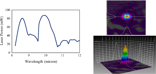
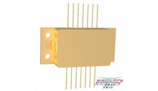
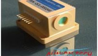
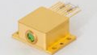
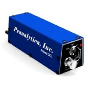
We used a QCL system that can be tuned in the spectral range from 8.2 to 12.0 μm to characterize the transmission of the filters. In Table 2, we list the salient characteristics of an air-cooled, computer-controlled quasicontinuous wave (QCW) QCL system (Pranalytica Inc. model OmniLux-80-90-100-110). We used three laser diodes in this system as shown in Table 2. Each laser diode is single mode with very small sidelobes (<3% peak power as compared to main lobe). Figure 8 shows the measured QCL power spectrum and a typical beam profile of the QCLs as measured by an Ophir–Spiricon Pyrocam IV camera. A collimated TE-polarized incident laser beam that covers overall filter area was used to be consistent with the incident plane wave assumption made in the theory.
Table 2
Salient characteristics of QCL system.
| Laser | Spectral range (μm) | Pulse frequency (MHz) | Peak wavelength (μm) | Measured peak power (mW) | Beam diameter at 1 m in mm | Output beam |
|---|---|---|---|---|---|---|
| QCL 1 | 8.20 to 9.59 | 1.0 | 8.6 | 81 | 5.2 (major) | Collimated |
| 4.4 (minor | ||||||
| QCL 2 | 9.60 to 10.70 | 1.0 | 9.9 | 88 | 5.1 (major) | Collimated |
| 4.4 (minor) | ||||||
| QCL 3 | 10.71 to 12.50 | 1.0 | 11.5 | 29.3 | 6.2 (major) | Collimated |
| 4.1 (minor) |
Fig. 8Download
Measured laser power and a typical beam profile of a QCL.
6.2.
Detector
An Ophir–Spiricon model Vega-B power meter with a 10A-PPS uncooled broadband thermopile detector with a 16-mm aperture was used to measure the intensity of light transmitted by the filter. The operation of the power meter is computer controlled.
6.3.
Filter Holder
The filter was mounted using two computer-controlled rotational stages. It can be rotated about an axis perpendicular to the filter plane to preciously line up the grating groove direction with the polarization of the incident light. The filter can also be rotated about a vertical axis parallel to the filter plane to adjust the angle of incidence.
7.
Performance Characterization Results
In Fig. 9, the measured transmittance spectra with TE-polarized laser light for a prototype filter with 1-D grating for four angles of incidence 0 deg, 9 deg, 15 deg, and 23 deg are shown, respectively. The graph shown here is acquired by measuring the average transmitted laser intensity at each wavelength for various filter tilt angles. Note that the high-frequency oscillations predicted by the RCW simulations are present in the measured data. Improved AR surface treatments will reduce these effects. As mentioned in Sec. 5, there is only one resonance notch for the normal incidence of light and there are two separate notches for non-normal incidence. In Table 3, we compare the values of resonant wavelengths obtained from both the computer simulation and experimental measurement. It is clear from this table that experimental values are close to the simulated ones considering the experimental error. We also observed in the measured data, however, reduced transmission at the longer wavelength (>10.5 μm) that is not predicted by simulations. We are currently exploring the reasons for this lower than expected transmission, but currently suspect it is greater than expected material loss at the longer wavelengths that are not accounted for in the model.
Fig. 9Download
Measured 1-D GMRF transmission spectra for TE-polarized light at four incidence angles: 0 deg, 9 deg, 15 deg, and 23 deg.
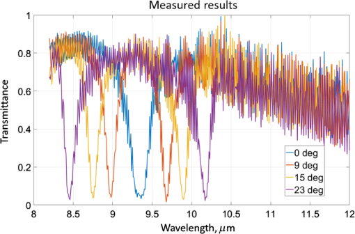
Table 3
Simulation and experimental values of resonance wavelengths for 1-D GMRF.
| Angle of incidence (deg) | Resonance wavelengths for TE polarization (μm) | |
|---|---|---|
| Simulation | Experiment | |
| 0 | 9.38 | 9.36 |
| 9 | 8.98, 9.72 | 8.98, 9.68 |
| 15 | 8.75, 9.95 | 8.75, 9.9 |
| 23 | 8.44, 10.26 | 8.46, 10.17 |
8.
Discussion and Conclusion
We designed spectrally tunable notch filters using the GMR phenomenon in a microengineered device with a subwavelength periodic Ge grating structure on a Ge planar waveguide deposited on a ZnSe substrate. Filters with 1-D gratings were designed to operate in 8- to 12-μm spectral region. As the notch filters with 1-D grating feature are sensitive to the incident polarization, we designed such filters for the TE-polarized light. Prototype filters were fabricated using standard dielectric deposition and photolithographic techniques. Such filters can be spectrally tuned by changing the angle of incidence by mechanically tilting the filter about the optical axis. We characterized prototype filters using a commercial room-temperature QCL system tunable over the 8- to 12-μm spectral region. Our experimental results match closely with the theoretical predictions. High-frequency oscillations in both the experimental and theoretical data were observed due to multiple reflections in the 1-mm-thick ZnSe substrate. The contribution from low QCL sidelobes to the noise is extremely small. The traditional method of characterizing spectral filters uses a Fourier transform infrared spectrometer (FTIR), which could not be used for our filters, as a collimated incident beam of light is needed to illuminate the filter, and is not available in a typical FTIR.
We used a simple two-layer AR coating on the backside of the substrate, which while not overly effective at reducing the high-frequency noise can be improved. We plan to improve the AR coating design using optimization techniques and are looking into using multiple layers and a wedged substrate. We are carrying out additional investigations to understand transmission losses due to the spectral dependence of the materials used.
We also plan on improving the filter fabrication process to improve the filter performance. We are upgrading a Bruker Vertex 70 FTIR to be able to take measurements with a normal incidence of light. This will facilitate rapid characterization of filters during and after fabrication process. We also plan to fabricate and characterize 2-D GMRFs to understand their spectral and polarization dependence in detail.
References
1.
S. S. Wang and R. Magnusson, “Theory and applications of guided-mode resonance filters,” Appl. Opt., 32 2606 –2613 (1993). https://doi.org/10.1364/AO.32.002606 APOPAI 0003-6935 Google Scholar
2.
R. Magnusson and Y. Ding, “MEMS tunable resonant leaky mode filters,” IEEE Photonics Technol. Lett., 18 1479 –1481 (2006). https://doi.org/10.1109/LPT.2006.877578 IPTLEL 1041-1135 Google Scholar
3.
R. Magnusson and M. Shokooh-Saremi, “Widely tunable guided-mode resonance nanoelectromechanical RGB pixels,” Opt. Express, 15 (17), 10903 –10910 (2007). https://doi.org/10.1364/OE.15.010903 OPEXFF 1094-4087 Google Scholar


