5G/NR - OTA (一)
OTA (Over The Air)
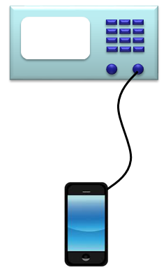
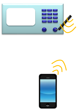
OTA stands for Over The Air. In order to perform test a device with any test equipment, you need a way of connecting the device to the test equipment. OTA is a kind of method connecting a device to a test equipment. There are roughly two kinds of connection method as shown below. One is Conductive and the other one is Radiative (or OTA). Simply put, OTA is a connection method via a pair of antenna (Transmiting antenna and Recieving Antenna).
5G OTA测试方案或附件需求,随时联系伽太科技,sales@gamtic.com,021-5197 0121.
Conductive | Radiative / OTA |
|
|
Actually OTA is a very complicated topic. There are many different aspect to think of. I will try to cover as many different perspective as possible as I learn and experience more.
UE Placement in Test Setup (Antenna Distance between UE and Test equipment)
Handling Known-D situation and Unknown-D situation (Whitebox vs Blackbox Approach)
When we say Radiative testing, it usually refers to various different types of configurations as shown below. These are just a few typical examples that you may see most often, but these are not all. There are so many different variations of Radiative Test Setups. Even though the terms OTA Test and Radiative Test can be used interchangeably, when we say OTA test without any specific details, we normaly think of the configuration like (C) or (D) shown below. As shown below, it is test in a chamber lined with absorbers (this kind of chamber is called Anechoic chamber. Anechoic means 'No Echo'. 'No Echo' in this case mean 'No reflection from any object in the box).
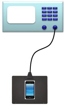
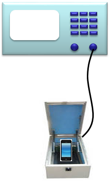
(A) | (B) |
|
|
| This may be one of the simplest way. We use a wide planar patch antenna and put the DUT on top of the antenna pad. Very convinient for the test like protocol or function test which does not require accurate RF measurement. However, unless you does not use this setup within a shield room, it may suffer from the interference from surroundings (e.g, from live network or other equipment) | In terms of Antenna setup, this is almost same as (A). But in this case the antenna pad and UE is within a small RF chamber. The benefit of this type comparing to (A) is that it can block the interference signal(e.g, interference from live network or neighbouring equipment) |
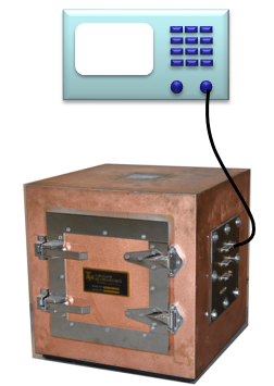
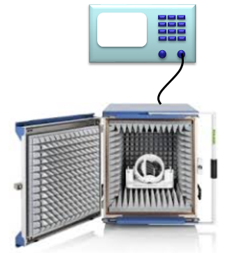
(C) | (D) |
|
|
This is a chamber made up of a conductive metal (usually copper). As in (B), this can block the interference from surroundings and at the same time it can reduce the interference from reflections in side of the box. When a electromagnetic wave from DUT or equipment hits the conductive wall, large portions of the wave can be obsorved by the conductor. | This would be the ideal solution for OTA test which requires a certain level of measurement accuracy. It is lined with special absorvers and usually has positioner in it which can change the direction of the DUT by external conroller. |
Even in conventional technologies (e.g, UMTS, LTE), sometimes we performed OTA measurement especially for TRP or TISmeasurement. However, in 5G/NR we are talking about OTA with almost every test, even with protocol test. Why OTA has become such a big issue in 5G/NR ? In NR, there are roughly two separated spectrum that are specified in 3GPP specification. One is FR1 (sub 6 Ghz) and the other is FR2(mmWave). In FR1, we may continue to go with the conductive testing as we do with 2G/3G/4G technology. However, in FR2 it is highly likely that we are forced to go with OTA. Why ?
We can think of several reasons for this and with a few different aspect.
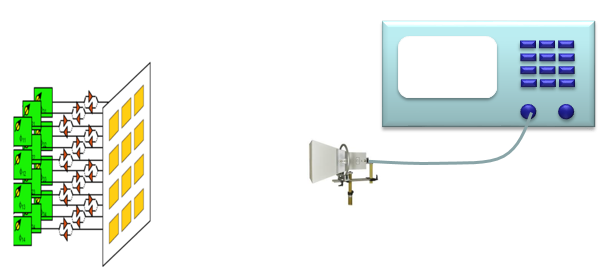
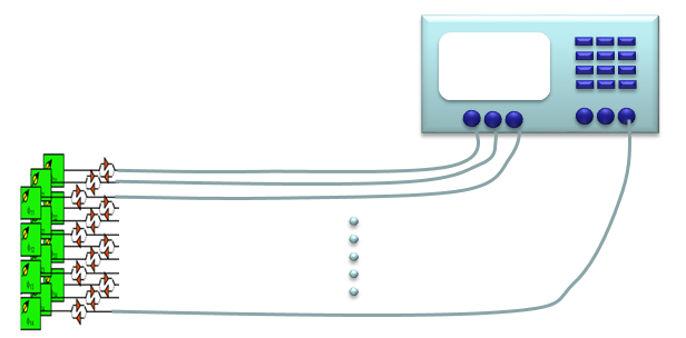
Complexity : In FR2, it is almost sure that we will use some type of array antenna (called Massive MIMO). It means you will have a lot of antenna on the device. If you want to go with conductive testing, the connection would goes like (B) shown below, whereas you can do test as in (A) if you go with OTA. Then, it would be obvious on why we want to go with (A). NOTE : If you want to ask why we need to use an Antenna Array, Motivation of Massive MIMO page would give you some insight.
Not Enough Space : Let's assume that you have enough reason to go with OTA despite the complexity of cable connection, you would still face another serious issue. Even though many of the antenna element (e.g, 16, 32, 64 etc) in your antenna array, the whole size of the antenna module would not be large enough at mmWave frequencies to accommodate all the cable connectors.
Cost : Now let's assume that you have really, really serious reason to go with conductive (like B) despite all the complexity and space issue. Even in this situation, there is other problem with conductive test. In most of conventional test, you might have used low cost SMA connectors and cables. However, you would not get the accurate measurement with SMA type of connector / cables in mmWave. You would need K connector or even more special connectors and cables (e.g, V connectors) if the freuqency goes even higher. These types of special connectors and cables cost much higher than those SMA types. If we need to use very high frequencies (like over 60 Ghz) in the future, you may need to spend in just for connectors and cables almost as much money as a low cost equipment price.
Physical Nature of the Measurement : Even when you overcome all the issues described above, there is certain types of measurement that requires OTA because of the nature of the measurement itself. For example, if you want to detect the direction of the beam formed by the antenna array, you must rely on OTA measurement. You may say that you can still do this by conductive test. Theoretically, you can bring all the signals from each of antenna element path down to baseband and figure out beam direction (and other nature of the beam) by baseband processing. Of course, theoretically this is possible. But I am 100% sure that you want to avoid doing this if there is a relatively easy way like OTA test.
(A) |
|
(B) |
|