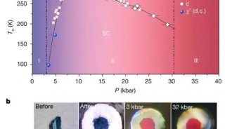
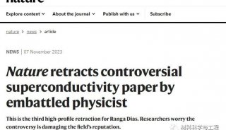
EMC Antenna Parameters and Their Relationships(一)
*originally published in June 1997.
Introduction
The basics of the EMC profession often get buried under the day-to-day effort of continuous measurement and the volume of test and reporting paperwork. The fundamental parameter of the most common of technical tools, the EMC antenna, is used over and over without thought as to its actual meaning. This parameter is the antenna factor (AF). A review of the basics behind this parameter, and a related parameter, the transmit antenna factor (TAF), provides a basis for the use of the numerical values, and a more fundamental understanding of radiated EMC measurements.
EMC Antennas
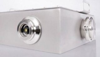
EMC antennas are used for EMC measurements in rather rugged environments involving frequent handling, rapid replacement with a different antenna for another frequency band and the normal wear and tear of day-in, day-out usage, two shifts a day, six days a week, in almost all weather conditions.
For all their apparent simplicity, antennas used in an electromagnetic compatibility (EMC) laboratory are as specialized and as sophisticated as antennas for any other application. These antennas are different in that their application makes broad bandwidths the most important design parameter, and gain, efficiency, and low input voltage standing wave ratio (VSWR) become secondary. Broad bandwidths are driven by the broad frequency spectrum covered in the performance of EMC radiated emission and immunity measurements.
The antenna parameters that are familiar to most antenna designers are then secondary design objectives in the development of these antennas. For all the importance of the bandwidth, however, the antenna parameter most often used, the AF, does relate to the performance of the antenna. The AF is used to quantify the value of incident electric fields, and its companion parameter, the TAF, is used to determine the value of the electric field at a known distance from the generating antenna.
EMC antennas are used for two types of measurements: radiated emissions (RE) and radiated immunity (RI). In the first case, formal calibration of the antenna and the use of traceable standards are required. In the second case, calibration is not required as the calibrations are usually performed as part of a complete EMC test setup. Each of these types of measurements employs a separate descriptive parameter. For radiated emissions measurements, the parameter is the AF. For radiated immunity or susceptibility measurements, it is the TAF.
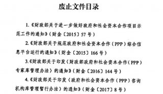
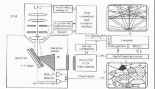
These two parameters are illustrated in Figure 1. This figure also illustrates other relationships between parameters used in the following derivations.

Figure 1. The relationship between antenna parameters.
Antenna Factor
The antenna factor is the term applied in radiated emissions testing to convert a voltage level fed by a transducer to the input terminals of an EMI analyzer into the field-strength units of the electromagnetic field producing that voltage.1 It relates the value of the incident electric or electromagnetic field to the voltage at the output of the antenna. For an electric field antenna, this is expressed as

where
AF = antenna factor, m-1
E = electric field, V/m
VL = voltage at antenna terminals, V
The AF is usually expressed in dB and when used to determine the value of an incident electric field, the expression is:

The derivation of the AF is straightforward and is based on several fundamental relationships in antenna theory. The relationships can be stated as: The ratio of power in the terminating resistance to the power density of the incident wave is defined as the effective aperture.2
Thus:

-
并购

-
焦点事件

-
会议会展

-
焦点事件

-
企业风采

-
企业风采

-
焦点事件

-
焦点事件

-
焦点事件

-
企业风采

-
焦点事件

-
焦点事件

-
焦点事件
-
产品技术
-
焦点事件

-
焦点事件

-
焦点事件

-
焦点事件

-
科技前沿

-
科技前沿

-
企业风采

-
焦点事件

-
焦点事件

-
焦点事件

-
精英视角

-
焦点事件

-
技术原理
-
焦点事件

-
综述

-
精英视角

-
焦点事件

-
综述

-
焦点事件

-
焦点事件

-
焦点事件

-
焦点事件
-
焦点事件
-
焦点事件
-
焦点事件
-
焦点事件
-
焦点事件

-
焦点事件

-
焦点事件

-
焦点事件

-
焦点事件

-
焦点事件
-
焦点事件
-
焦点事件